![]()

|
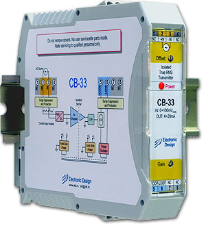
Introduction The CB-33 isolation transmitter measures the effective values of AC or current (True RMS to DC). The module converts, amplifies, isolates, filters and re-converts the voltage signal to an output current of 4 to 20 mA. These types of transmitters are electrically powered through the same two conductors used to transmit signals, so in practice they are termed two-wire. They are suitable for transmitting signals up to 1200 m to the data acquisition system, industrial PC, PLC or some other measuring system.
CB-34 isolation modules protect people and measuring equipment and physically separate them from ecstatic events that may appear on the sensor side or somewhere else within a measuring environment. The module inputs are protected from transients and voltage levels up to 500 Vrms and output to 250 V AC. The transmitters have a very low price and excellent features that meet only in very expensive models.
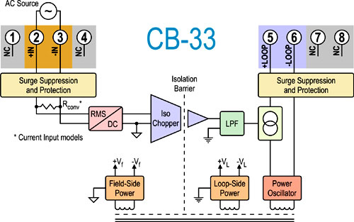
The voltage or current input signal is processed through a pre-amplifier and RMS converter. The signal is then filtered and transmitted through an isolation barrier by an amplitude modulation technique that provides high linearity, stable and reliable characteristics. After isolation, the signal is reconstructed by a fourth-order filter and converted to a standard current or voltage output level. This architecture provides excellent linearity, stable and reliable characteristics and does not require input grounding. The signal demodulator on the output (secondary) side of the module restores the original signal, which is then filtered and converted to a 4 to 20 mA current signal.
Characterization The input circuit provides overvoltage protection up to 500 VAC and protection against transients defined by ANSI / IEEE C37.90.1-1989 documents. The transmitters have a fifth-line filter, which suppresses 50 Hz with 80 dB. The power supply of the transmitter is via a two-wire current loop in the range of 11 to 60 V. The power supply module of the circuit has a built-in protection circuit for inverse connection of the supply voltage and circuits that prevent passage of transitions. The module has excellent stability in time and does not require calibration or any maintenance. On the front of the module below the front sticker there are two multi-port trimmers for precise adjustment of the offset and gain. Both values are set before delivery, and the user can overbalance these values according to their needs in the range of ± 10%. Transmitters can be switched on and off from the measuring system without switching off the supply voltage or system shutdown.
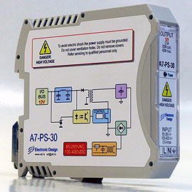
Power supply for transmitters
For power supply up to 50 transmitters, the CS-PS-48, 48W power supply (left-hand) is recommended, while the power supply of a number of conditioners should use a CS-24-90 of 90W source, which can, under full load, power up to three times more transmitters, although such a large number of transmitters are recommended to be powered from multiple el. sources. Transmitters do not support the rail T-BUS connector because they are powered through a loop.
The CS-PS-48 source operates in a wide voltage range from 85V to 265V AC. Both power sources operate in a wide voltage range from 160V to 265V AC. If the user does not want to use this type of power, it can also use other electrical sources.
Picture to the left: Power supply for CS-24-30 transmitters
Specifications and characteristics (tipically at 25°C)
Prices and types
Prices are without VAT
Option 1. Transmitters typically have a frequency band of 3 Hz. For a bandwidth of 1 kHz or 10 kHz (-3 dB), the price is 3 € higher. Option 2. Commodity-protected transmitters for high-humidity environments have a 10 € higher price. Option 3. Transmitters artificially tested with the Burn-in process, 48 hours at 60°C have a 15 € higher price. Option 4. Transmitters by special user specification: the first piece is 150 €.
Back
to Page "CB Series Transmitters"
|
||||||||||||||||||||||||||||||||||||||||||||||||||||||||||||||||||||||||||||||||||||||||||||||||||||||||||||||||||||||||||||||||||||||||||||||||||||||||||||||||||||||||||
|
© 1982 -
Electronic Design Makenzijeva bb-Pejton, Beograd |
Tel: +381 11 308 50 30 Fax: +381 11 308 50 31 |
Tel: 011 2 450 480 Tel: 011 308 74 59 |
|