![]()
|
CA 38 Measurement bridge conditioners |
|
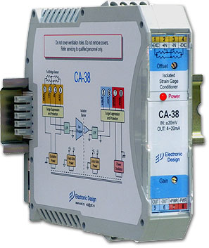
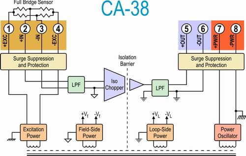
GeneralThe CA-38 is an isolated signal conditioner for measurement bridges. It amplifies, filters, excites, isolates, and converts an input signal into an output suitable for connection to a data acquisition system, Industrial PC, PLC, or other measurement system. The CA-38 has an isolated excitation for supplying voltage to a measurement bridge with a nominal resistance of 100 Ohms to 10 kOm. The measuring bridge is driven by a stable voltage of 10.00 V for measuring bridges from 300 Ohms to 10 kOhms, or 3.33V for measuring bridges from 100 Ohms to 10 kOhms. The excitation source is isolated by a transformer. The input load can be grounded or non-grounded. CA-38 isolated conditioners protect people and measuring equipment, and galvanically separate it from excessive events that may occur on the sensor side or elsewhere within the measurement environment. The module input is protected from voltage levels and transients up to 250 Vrms. The isolation voltage is 1500 Vrms continuously. The CA-38 signal conditioner family can be mixed with other isolated module families within the same application. They can be plugged into and off the measuring system without switching off the power supply voltage or interrupting the system (Hot swapable). Special input circuits protect signal input and excitation from accidental connections with voltage lines up to 250 V AC and against transients according to ANSI / IEEE C37.90.1 specifications. Also, protective circuits are located on the output connections of the conditioner. The signal and voltage conductors are connected to the module over screw terminals.
CharacterisationThe central component of the module is the signal isolation transformer. Like most transformers, this one has a primary and a secondary side. Using this terminology, the input side of the module is "primary side" and the output side of the module is called "secondary side". A sensor is connected to the primary side of the module and the secondary side of the module is connected to a data acquisition and measurement system, an analog input module of an Industrial PC or PLC, to a panel meter or other measuring system. Transformer signal isolation uses an amplitude modulation method to obtain linear, stable and reliable characteristics. This technique produces better results than digital or linear optocouplers or capacitor isolation techniques. The primary side of the module is galvanically isolated or "floating" relative to the secondary side of the module and relative to the power supply. The signal demodulator on the secondary side of the module restores the original signal, which is then filtered and buffered to achieve low noise and low output impedance. CA-38 series isolated modules have a fifth-order filter built in. The first anti-aliasing filter being located in the primary circuit of the module while a fourth-order filter is located on the secondary side of the isolation barrier. After anti-aliasing filtering, the signal is brought to the chopper stage behind which is a specially designed micro transformer. On the secondary side, behind the isolation barrier, the signal is demodulated and re-filtered from transmission spikes and interference. The output of the module can be a voltage or current signal as needed. Voltage excitation ensures accuracy within 0.01%. The voltage regulation circuit is galvanically isolated from the input, output and power supply and is protected from external voltages up to 250Vrms. For higher voltages, protection is applied which shorts the output terminals without harming the excitation circuit. The warranty period is 7 years and the service period is 10 years. It comes with a user guide in English and a calibration list. CA-38 with 110/220V AC power supply (option)
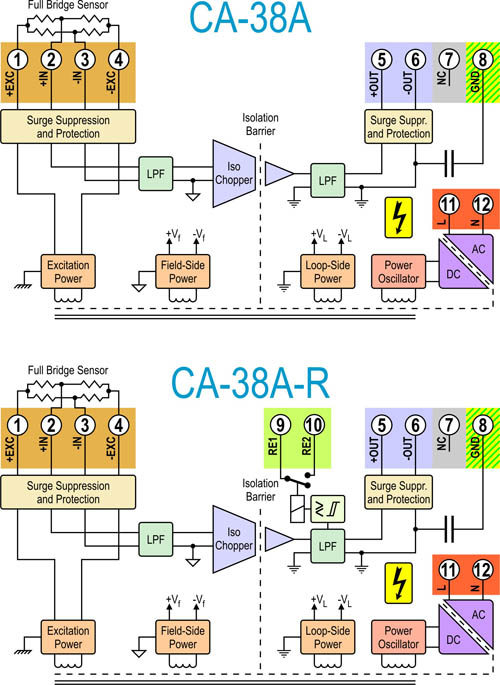
This type of signal conditioner works with an AC voltage of 85 to 265V or a DC voltage of 100 to 400V. These two power ranges make the CA-38 applicable in many situations. Some users use these conditioners in an environment powered by a 110V battery, or under conditions of elevated AC voltage in the substations. There are three power connectors on this conditioner model: L, N and GND (Left picture). Phase must be connected to L, N to zero, and GND to ground. In addition to the safety function, grounding has the function of reducing the oscillations of the internal voltage unit, so it should be connected in any case. If DC power is used, it must be connected to the L and N terminals (order does not matter). Relay (option)The CA-38 R-type isolated family of conditioners has a built-in relay with normaly open and normaly closed contact on the external connections. The relay can turn on or off up to 240V, 6A, and can be set to activate when the input signal is larger than the set value or when it is less than the set value. A hysteresis control is installed for the relay. Activation can be fine-tuned with a precision multi-turn trimmer potentiometer. The only limitation with this version is that if it is used with 220V power supply (version with suffix A), the relay only has a normaly open contact. The activation level of the relay is adjusted by a potentiometer on the front of the conditioner. To avoid oscillating the relay when the input is equal to the setpoint, there is a hysteresis in the circuit. Hysteresis in the first case, when the relay is activated and when the input is greater than the set value, indicates the level by which the input signal should be smaller than the set size to activate the relay to switch it off, In the second case, indicates how much the input signal should be higher than the set point to turn the relay off. The hysteresis can be adjusted to 1% or 5% of the span by an internal jumper. If the load that is connected to the relay is inductive, then a "snubber" must be added externally parallel to the relay contacts. The values of the snubber components are calculated, but can also be determined empirically for a given application. Generally, even if the load is connected to an inductive type relay, a 0.2 uF capacitor can be used with a 10 ohm resistor. For optimum performance, the snubber circuit should be calculated as it is the best way to optimally quench the spark on the relay. Power supply and T-BUS connector
Both power supplies work in a wide voltage range: CS-24-90 from
160V to 265V AC, while smaller, CS-24-48 can operate as much as
85V to 265V. If users do not want to use this type of power
supply, they can also use other power supplies, but in this
case, the power supply must be wired from one conditioner to the
other by cables. Picture on the left: Power supply CS-24-48 for conditioners with T-BUS connector
SpecificationsTypical (25°C)
|
||||||||||||||||||||||||||||||||||||||||||||||||||||||||||||||||||||||||||||||||||||
|
© 1982 -
Electronic Design Makenzijeva bb-Pejton, Beograd |
Tel: +381 11 308 50 30 Fax: +381 11 308 50 31 |
Tel: 011 2 450 480 Tel: 011 308 74 59 |
|
 The basic version of the CA-38 works with a standard DC power supply of
19 to 30V DC (24V DC nominal). However, if the application requires power
from 110V or 220V AC mains, which is not a rare case, then the user can
order the conditioner with suffix A.
The basic version of the CA-38 works with a standard DC power supply of
19 to 30V DC (24V DC nominal). However, if the application requires power
from 110V or 220V AC mains, which is not a rare case, then the user can
order the conditioner with suffix A.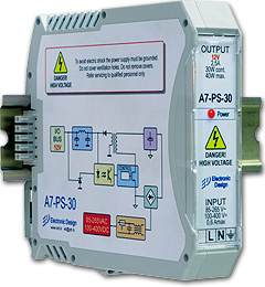 For the power supply of a smaller number of conditioners up to
20, a CS-24-48 that delivers 48W is recommended (picture on the
left), and for greater number of conditioners a CS-24-90 of 90W should
be used. Both models can, via the T-BUS connector be
connected, directly, without wiring to power the conditioners on
the same, or with the extension cable, on different DIN rails in
a closed environment. This option raises reliability, greatly
reduces the time of replacement of the conditioner and allows
the conditioner to be connected or disconnected while the T-BUS
is powered up.
For the power supply of a smaller number of conditioners up to
20, a CS-24-48 that delivers 48W is recommended (picture on the
left), and for greater number of conditioners a CS-24-90 of 90W should
be used. Both models can, via the T-BUS connector be
connected, directly, without wiring to power the conditioners on
the same, or with the extension cable, on different DIN rails in
a closed environment. This option raises reliability, greatly
reduces the time of replacement of the conditioner and allows
the conditioner to be connected or disconnected while the T-BUS
is powered up.